
The end-fed half-wave antenna has been the most-read topic on this website for as long as it has existed. No POTA report, no app presentation comes close to the end-fed building guides. And I understand why: one wire, one suspension point, a little box with a toroid inside — that’s all it takes for five bands.
Over the years I’ve built quite a few variants. With a 1:49 unun, with a 1:64, for 40 to 10 m, as an eight-band version for 80 m. And whenever someone at a field day asked me which unun was the right one, I answered truthfully: «Both work.» Why both work, and when which one is the better choice — hand on heart, I had never properly looked that up. After the story with the delta loop I wanted to know. This time before anyone asks.
The starting point: a bet on an unknown number
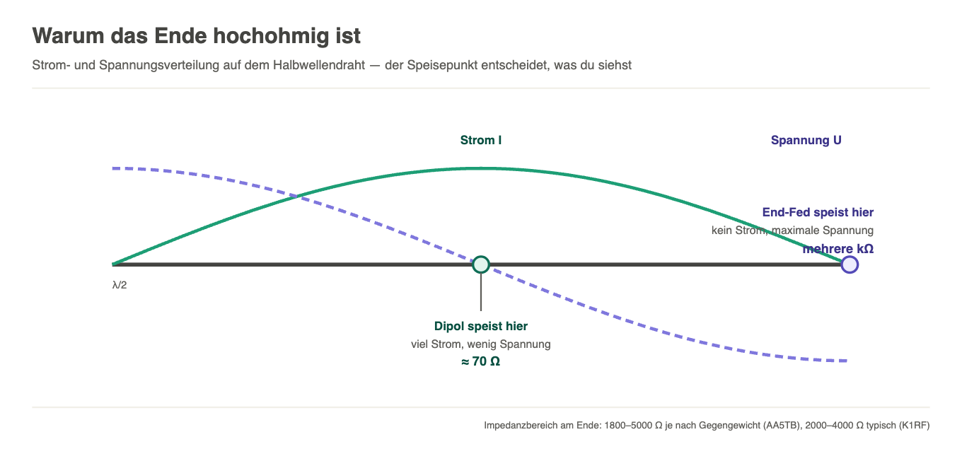
A quick bit of physics, then the rest gets easy. A half-wave wire carries a standing wave: the most current flows in the middle, the highest voltage sits at the ends. The dipole is fed in the middle and shows around 70 ohms there. The end-fed is fed at the end — where almost no current flows — and therefore shows the opposite: several thousand ohms.
Exactly how many thousand, nobody knows in advance. AA5TB modelled it and, depending on the counterpoise, arrives at 1800 to 5000 ohms; K1RF quotes 2000 to 4000 for typical installations. The impedance depends on the mounting height, the surroundings, the wire and above all the counterpoise.
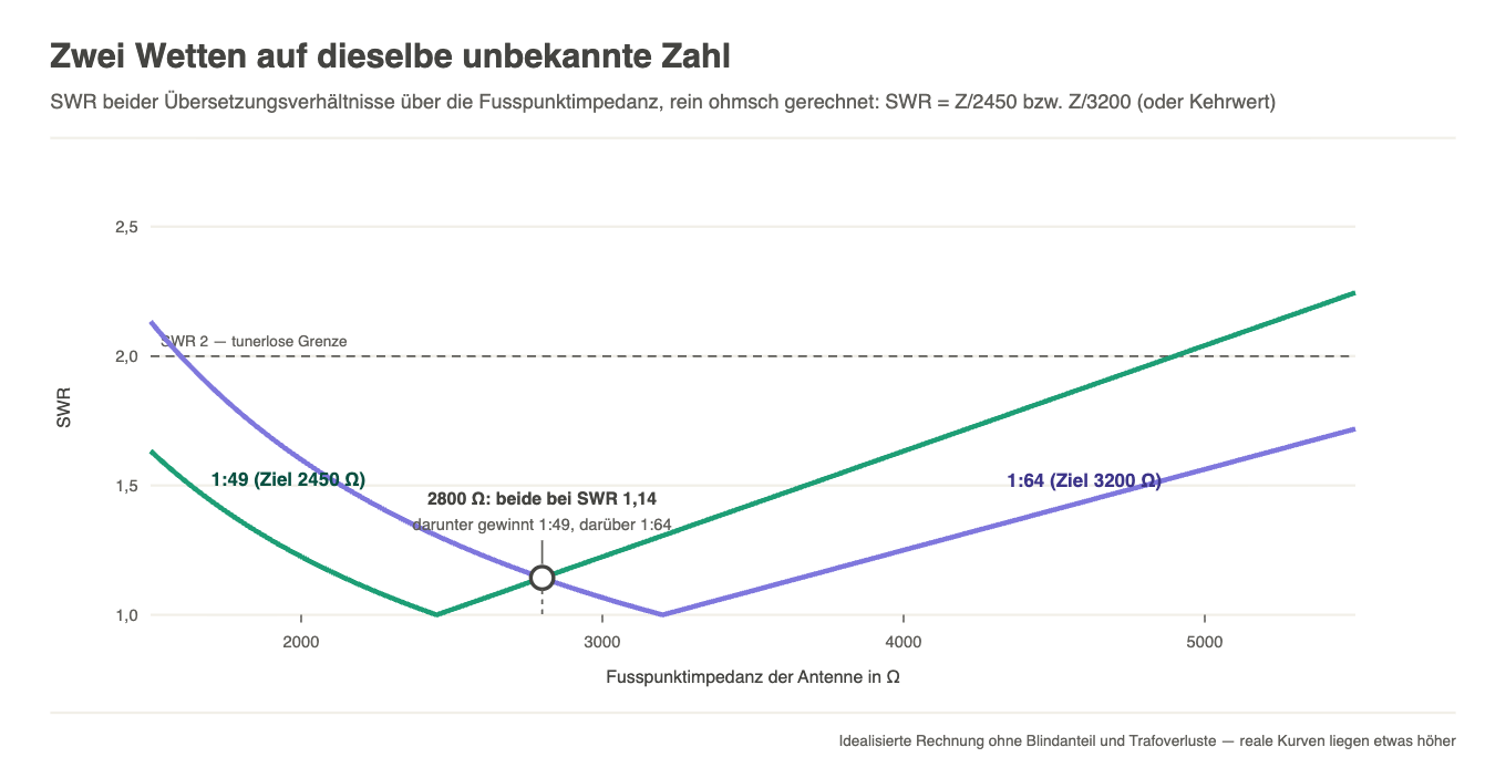
And now the point that had never been that clear to me before: a fixed-ratio unun is a bet on a number you don’t know. The 1:49 bets on 2450 ohms (49 × 50), the 1:64 on 3200 ohms (64 × 50). If neither wins the bet exactly — and neither ever does — you pay with SWR.
The maths behind it is pleasantly unspectacular
If you work out the SWR for both ununs across the whole realistic impedance range (assuming a purely resistive load; the calculation is below the chart), something reassuring happens: the two curves cross at 2800 ohms — the geometric mean of the two target impedances — and there the SWR for both is a harmless 1.14. If your antenna is below that, the 1:49 wins. If it’s above, the 1:64. And across large parts of the range both stay below an SWR of 2.
That is the sober reason why my field-day answer «both work» has been right all these years. The end-fed is forgiving when it comes to the choice of unun. If you swap back and forth between the two variants and hardly see a difference, you’re not imagining it — the difference is small.
Small, however, is not zero. There are two situations in which the choice tips.
When the 1:64 wins
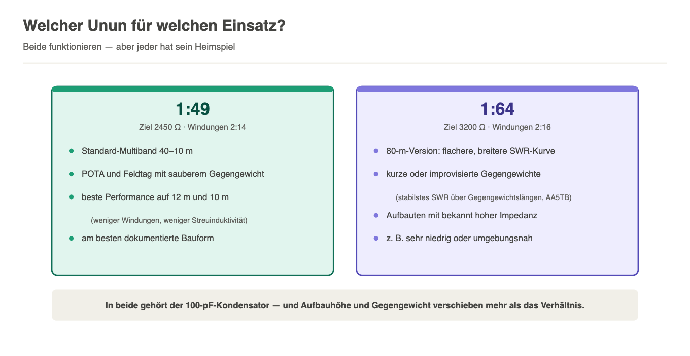
First: short or improvised counterpoises. AA5TB’s modelling shows that the impedance wanders with the length of the counterpoise — from around 1800 ohms up towards 5000 as the counterpoise approaches a half-wave. And it shows something else: across this whole span, the 8:1 turns ratio — in other words the 1:64 — delivers the most stable SWR. If, like me at a field day, you often simply let the three metres of coax act as the counterpoise, the 1:64 gives you the more fault-tolerant antenna.
Second: 80 m. The 80 m end-fed is a sharp resonant circuit, with the good SWR window often only 80 to 100 kHz wide. The slight mismatch of the 1:64 lowers the Q of the system and flattens the curve — the minimum gets a little worse, but in return a much wider slice of the band stays below an SWR of 2 and can therefore be used without a tuner. My technical guide from last October also describes this effect in more detail.
When the 1:49 wins
On the higher bands. The 1:64 needs more secondary turns (2:16 instead of 2:14), and every additional turn brings leakage inductance and winding capacitance with it. On 40 or 20 m that hardly matters. On 12 and 10 m it does: in a very worthwhile series of measurements, Gary Rondeau AF7NX showed that precisely these parasitic effects limit the transformer’s high-band behaviour — and that they grow with the number of turns. Fewer turns, better 10 m behaviour. Advantage 1:49.
On top of that there’s a practical point: the 1:49 is by far the best-documented variant. If you’re winding one for the first time, you’ll find ten times as many build reports, measurements and failure patterns as for the 1:64.
The trap that snaps shut with both
While researching, I stumbled over a point that matters more than the whole 49-versus-64 question: a good SWR does not prove that the antenna is good. A lossy transformer acts like an attenuator — it swallows transmit power on the way out and reflected power on the way back, and the SWR meter shows a flatteringly good picture. AF7NX measured the core losses systematically: material 43 is at its most forgiving around 7 MHz; towards the higher bands the losses rise, depending on the build into the range of several dB. Three dB means half the power heats the toroid instead of the antenna.
Between a cleanly wound 1:49 and 1:64 there’s no fundamental difference in efficiency — the losses depend on the core material, the frequency and the build quality, not on the ratio. The 100 pF capacitor across the primary winding belongs in both, otherwise 15, 12 and 10 m collapse. And if your unun is hot after a digimode session, you now know where your power went.
My verdict after umpteen antennas and an evening of research
For the standard end-fed from 40 to 10 m, the kind that hangs from my mast on POTA activations: 1:49. It matches the typical impedance well, loses the least on the higher bands and is the best-documented route.
For the 80 m version and for installations with a skimpy counterpoise: 1:64. The broader 80 m curve and the stability with respect to the counterpoise are exactly the right properties there.
And in both cases: the mounting height and the counterpoise shift things more than the choice of ratio. If you swap your unun but hang the antenna the same way, you’re changing the least important thing first.
Finally, the usual honesty: the figures in this post come from the published measurements and models of AA5TB, K1RF and AF7NX, not from my workshop — I’ve built, hung up and used my own ununs so far, but never measured them side by side. Of course, that’s tempting me now. A 1:49 and a 1:64 on the same wire, same mast, same afternoon, analyser connected: that would be the honest part 2. The building instructions for both variants, by the way, are in the technical guide here on the website — and you’ll find the variants I’ve built in the categories End Fed with 1:49 and End Fed with 1:64.
73 de Chris, HB9HJI
Leave a Reply