Alternate fan mod for IC-7000
Contact author: M3SVO
!! IF YOU ARE UNSURE ABOUT PERFORMING THIS MOD DON’T!!
!!IF YOU DAMAGE YOUR RADIO YOU ONLY HAVE YOURSELF TO BLAME!!
I have performed this mod on MY OWN radio without any adverse affects and my LDG AT-7000 atu still works as it should.
Before this mod after been turned on for an hour or so the temp meter on the radio would show around 50% on the scale (7 or 8 bars), after the mod the temp meter shows around 25% on the scale (4 bars).
First remove the top cover and remove the fan from the radio,
take a 100ohm resistor and solder a length of wire to each end and cover with heat shrink tubing. Cut the red wire to the fan and attach one of the resistor wires between the two halves and cover with heat shrink tubing.
Next follow the ORANGE wire from the ATU molex socket on the back of the radio to where it is soldered on to the DDS unit (top right hand corner at the back of the radio) and attach the remaining resistor wire to this point, position the resistor and wires so that they look neat and tidy and then refit the fan and the top cover, mod is now complete.
Enable TV reception for ICOM IC-7000
Contact author: Duke – NA1A
Enable TV reception for ICOM IC-7000
Contact author: Duke – NA1A
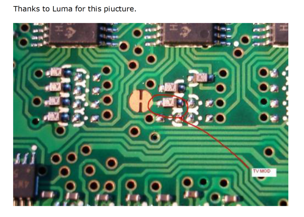
- Remove CPU/DSP unit by unscrewing three silver screws holding it down (the silver box on the top of the radio with copper taped sides) and pull up.
- Locate four shift registers and bank of diodes – shift registers are 4094’s. There are two next to each other and then a couple more. We’ll call the two stacked the “left” ones
- The “middle” shift register if looking from the front of the radio is the target.
- Locate bank of SMT diodes (silver with “K” on top on one side) in front of the target shift register. They are in two columns, “left” and “right”
- Unsolder one side of the second diode from the front on the left and lift up one side (or remove, slip to the side, whatever turns you on)
Fan Mod – Cool as ice
READ ALL OF IT BEFORE PREFORMING THE MOD!
Use a baby thermometor ( the electric kind w/ the digitial readout ) and see just how hot your rig is running before preforming the mod, I know most all of my readings were over 106F then the thermometer errored out as the temp was too high.
Tempurature Measurements were made with a baby-tempurature thermometor ( sorry its all I had at the time ).
Heres the Proof!
top – left front 94.6F
top – left rear 103.8F
top – right front N/A (below 85.5F unable to get reading)
top – right rear 92.7F
Right side front 90.6F
Right side rear 91.5F
Left side Front 95.0F
Left side Rear 98.1F
After cw keying for aprox 5 min continous duty the heat generated by the IC-7000 did rise enough to enable to the temp control circuit. Heres the good news!
Once the temp control circuit kicks in, the fan goes into high-rpm mode!!! Then returns to ‘normal’ operation with the 2W / 100ohm resistor voltage.
So with this mod, you get a dual speed fan without any additional modifications!!
Forgot to mention, when you goto solder the lead to the red wire of the fan, please place a rag or something undeneath the area you will be working in ( its pretty tight ) to prevent any unwanted solder dripping down onto the main board.
When closing everything all up, there is a little pink sticky pad ontop of the cover unit to access the mars/cap and tvro mod. Place your wire so its right on top of the sticky pad. Seemed to be the best place for it at the time.
Options, the Red wire from the fan connecter to the main board could be snipped between the connector and the solder joint to avoid any complications with the temp circuit enabling.
Additionally, the back left of the rig, still feels warm to the touch but its more of a luke-warm, instead of what it was previously which was excessivly hot. The back right, front left and front right all feel cool to the touch.
Im sure there are better ways of preforming this modification, although just stealing 0.14A from the 12v+ DC on the tuner port seemed to make the most sense, since an LDG Tuner only uses 300mA when in operation.
Although I do not know how this will affect the autotuner as I do not have one, I am unable
to test this modification with an autotuner, such as the LDG Z11 or Z100.
Your Icom 7000 Running Hot? … Heres the FAN mod! ( This has been untested with an inline tuner )
- Tuner Lead #3 is +12v DC, tap into Tuner Lead #3 with a wire ( theres enough room to simply slip a solid copper wire into the crimp for lead #3 )
- Add a 100ohm Resistor at the other end of the solid copper wire ( a 100ohm pot will work if you wish to be able to vary the speed of the fan )
- Strip the insulation of the red wire to the fan back just enough to make a solder connection to the 100ohm resistor / 100ohm pot. We used a lighter to burn away a bit of the insulation in the middle of the wire b/t where it connects to the board and where it connects to the fan itself.
Wrap it all up with some electrical tape to prevent grounding. and Whala! Your Done!!
Tuner Port on back of the IC-7000
^
1
2
3 +12v DC -> wire -> 100ohm resistor -> fan red wire
A 100ohm Pot could be used instead of a resistor, values below the 100ohms will increase fan speed.
0 resistance – sounds like an airplane.
How to fix the IC-7000 audio noise (hiss)
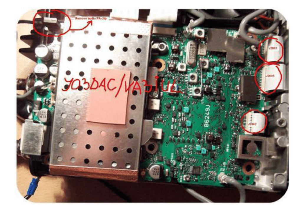
Contact author: Iulian Rosu YO3DAC / VA3IUL
This paper is about fixing the IC-7000 noisy audio that occurs only when the audio output is connected to high-fidelity earphones. This audio noise (which sound like a hiss or white noise), is even stronger if the earphones are connected to the external speaker connector on the back of the transceiver. The hiss (that is not the same as the 8 kHz tone issue) is very inconvenient especially when listen weak stations in CW and SSB and using high fidelity headphones.
What to do:
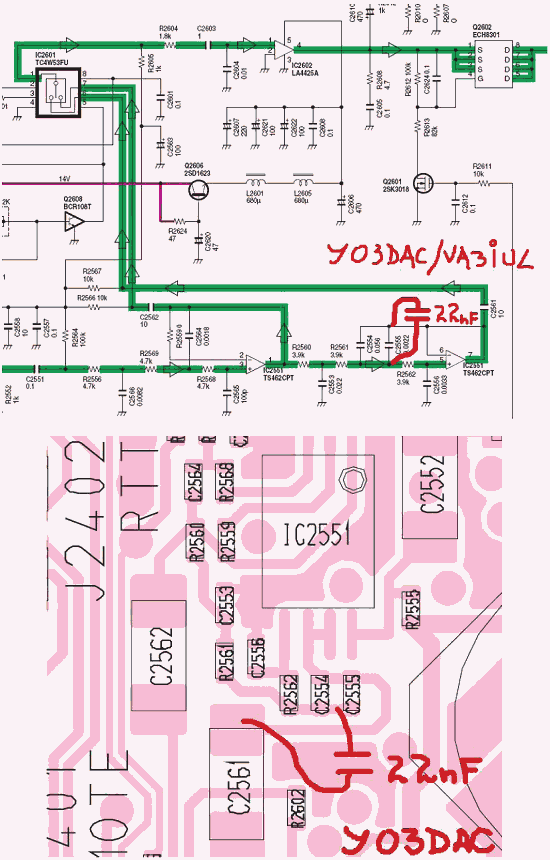
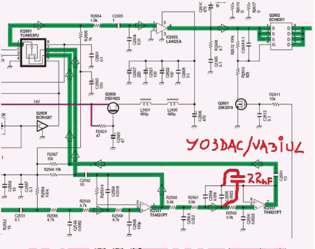
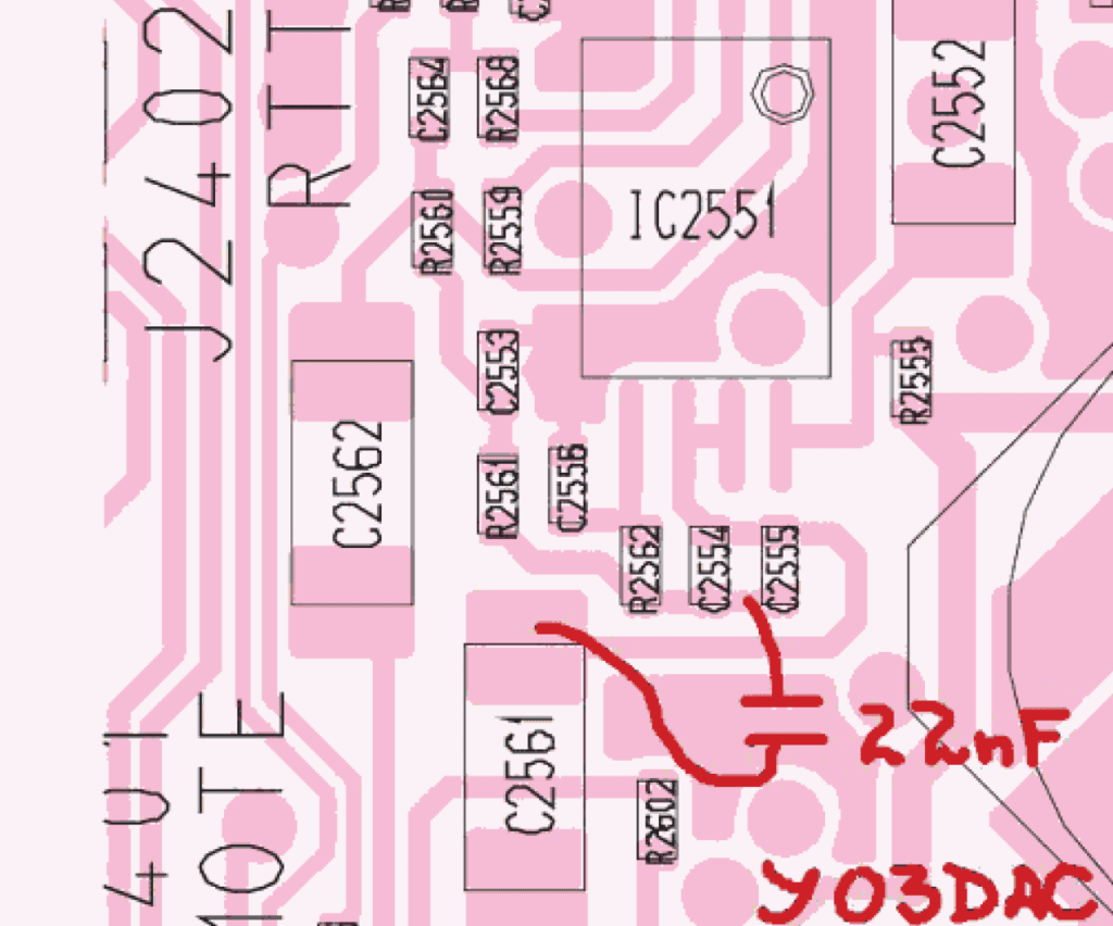
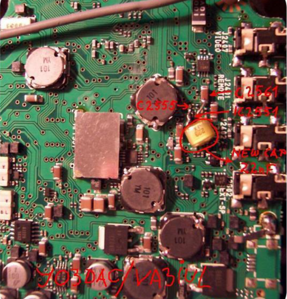
To fix this problem have to lower the cut-off frequency of the active audio filter (IC2551) which is placed before the audio power amplifier (IC2602).
How to do:
Remove the top cover of the radio and unplug the speaker.
Remove the spring clip of the audio Power Amplifier (IC2602 – see picture).
Remove the CPU/Logic unit (Silver box).
Remove the DDS unit (B6294L).
Remove all coaxial plugs and ribbon cables from the board. Be careful when removing the J2005 and J2003 ribbon cables as they can be pulled out of the PA unit. Would be very difficult to reinsert them into the PA unit.
Remove the Main Unit (B6249J) – The modification is done on the bottom of this unit.
Add a 22nF capacitor in parallel to C2555. You can solder one pin of this cap to C2561 (10uF) and one pin to C2555, or you can add an SMD (0402) 22nF in parallel to C2555.
Plug in the two ribbon cables from the DDS unit into the Main board before fitting the Main board to the chassis.
Replace all screws and tighten.
Plug in all the cables, re-fit the CPU/Logic unit.
Replace the top cover and plug in the speaker.
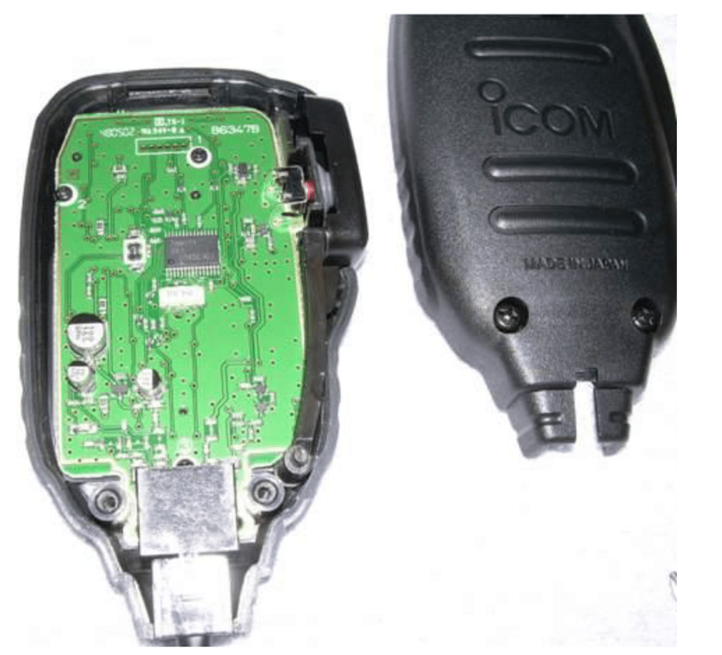
Icom HM-151 modifications (original IC-7000 hand mic)
I have experimented with the original hand microphone that comes with the IC-7000. One thing I noticed with the HM-151 is that (compared to the HM-103 etc) it has a lot of bass response, and this also depresses the treble response a bit. Sadly, the IC-7000 do not have the DSP TX equalizer that I feel should have been implemented. The IC-7000 is an excellent radio on transmit, but with the HM-151 it’s a bit to “bassy” and it sounds to muffled.
This can be improved by replacing the C30 ceramic capacitors inside the HM-151.
One can use the MIC RECORDING function in the IC-7000 and record exactly the same phrase before and after the modification to compare and hear the difference.
Remove the rear cover of the HM-151
The schematics below show the HM-151 internal circuit.
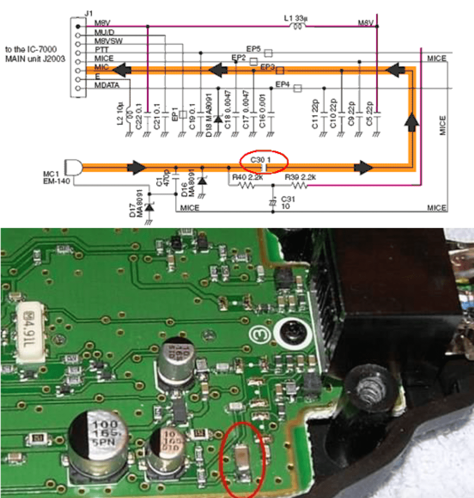
The serial capacitor C30 is responsible for the bass roll-off, and 0,22 F is in my opinion the best value. This value also works great for FM-mode. Decreasing it any further will cut away too much bass and it will make the HM-151 sound very thin and weak (with decreased output).
The original size of the C30 capacitor is 1 F, and this is a bigger value than in any other icom hand microphone I know of. This is why it will allow a lot of bass to pass through, and this is why it will sound “bassy” compared to other icom hand mics.
First, you must get your hands on the replacement capacitor.
The C30 capacitor should be replaced with a 0,22 F SMD ceramic capacitor called C3216X7R1H224K. Size/type is 3216 or 1206 (3,2 x 1,6 mm). (also named C1206C224K5RAC C-7025) ELFA part number : 65-777-04
Replace the C30 capacitor. It is a bipolar capacitor, so there is no + or – on it. Please be aware of the fact that soldering such tiny SMD components are VERY difficult, if you don’t
feel like doing it yourself I strongly advice you to contact an electronic service shop to do it for you. Be careful ! Buying a new HM-151 is expensive!
Mic gain at 80 – 100 % , COMP on level 1 only. Try these setting for transmitter bandwidth (TBW):
W(L) 100
W(H) 2900 W= Ragchew
M(L) 200
M(H) 2900 M= DX
N(L) 300
N(H) 2700 N= DX (sounds almost like Heil HC-4)
This way you will have good settings for both Ragchew and DX. Only use COMP if necessary
Note ! If your IC-7000 has been modified internally (microphone preamp.) you will probably not notice any difference with this modification. This is the case with most IC-7000 radios sold in Scandinavia. They sound good in SSB-mode, but a little low on bass in FM-mode. There is no need to modify these radios any further (leave them as they are). If you on the other hand are planning on buying a new IC-7000, ask for an unmodified radio (microphone preamp.) but let the dealer replace the C30 capacitor inside the HM-151 for you.
Good luck !
Increase the TX power of IC-7000